“Convert to Sheet Metal” allows the user to quickly convert parts into sheet metal models, from there a flat pattern can be automatically created. This is a useful tool if the initial part has been created using standard part modelling features such as extrudes and lofts. The tool also works well on imported Sheet Metal files, to use it simply follow these steps.
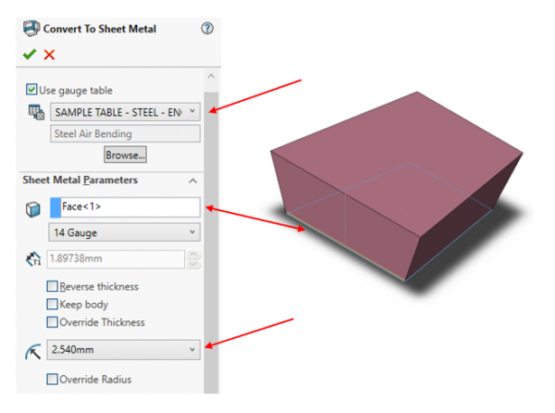
- Define the desired thickness and bend radius either by selecting a gauge table or by entering it manually. In this example, I have used a sample table for steel and selected 14 gauge with a 2.54mm bend radius.
- Select a fixed face, here I have selected the bottom face has been selected as the fixed entity. This decides which face the remaining faces are bent from.
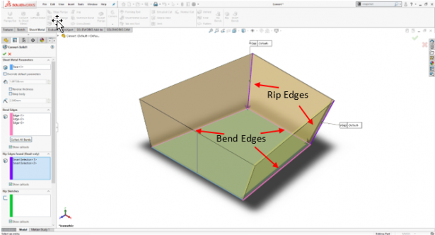
Select required “Bend Edges” to define the bends in the sheet metal part. SOLIDWORKS will then automatically select “Rip Edges” which create cuts in the sheet metal body.
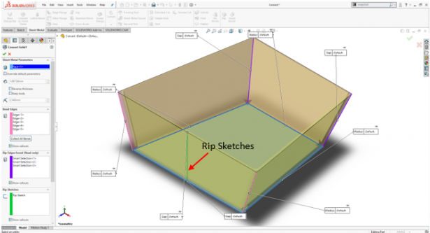
Due to the structure of this component it is impossible to bend the fourth edge to complete the shape,so we’ll need to use a “Rip Sketch”. A “Rip Sketch” will cause a “Rip Edge” to be added at a chosen location based on the geometry of the sketch.
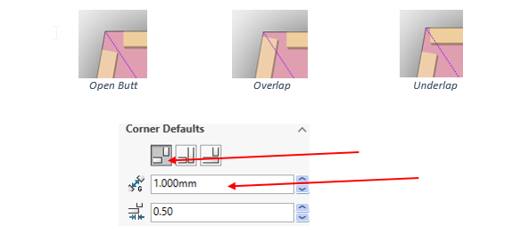
Where two edges meet the gap and type of corner; Open Butt, Overlap, Underlap, can be selected for all or individually. For this example, I have selected an Open Butt corner type with a 1mm gap
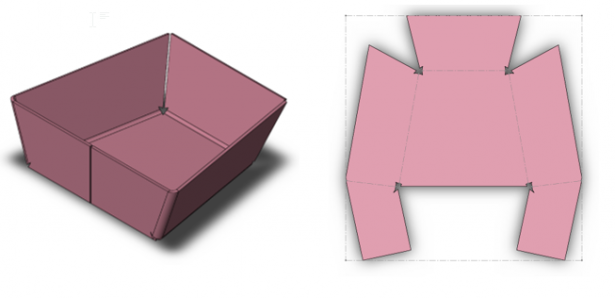
The part is now converted to sheet metal and can be viewed as a folded or flattened part.
To get more updates on SOLIDWORKS Follow Us on LinkedIn: Click Here
For more details Like Us on Facebook: Click Here
For videos SUBSCRIBE to our channel: Click Here
Get A Quote Today: Click Here