The purpose of the SOLIDWORKS CircuitWorks is to create solid models from ECAD files of types like PADS ACSII(. asc), or Intermediate Data Format (. emn) and then be able to add features, like mounting holes, then export back to the ECAD file format. This feature can be used to create enclosures and set aside space within assemblies.
What you will need to get started:
- SOLIDWORKS Professional or SOLIDWORKS Premium (CircuitWorks is not available in SOLIDWORKS Standard)
- ECAD files (.asc or .enm).
- CircuitWorks Add-in
To start CircuitWorks you must first open the drop-down to the right of the “Options” button
Then when the Add-ins window opens select the left checkbox to turn on the add-in and or the right checkbox to have the add-in loaded at startup.
Click “OK” to close the window and save the changes.
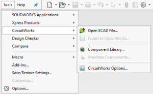
CircuitWorks is now added to the SOLIDWORKS “Tools” menu.
Next click on Tools – CircuitWorks – Open ECAD file.
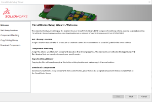
If you have never used CircuitWorks before, you will be prompted to run the “first use wizard”.
If you click “Yes”, this wizard will start:
Click “Next”.
Accept the defaults shown here:
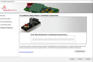
Click “Next”.
Click “Start Download”. This will populate the library from 3dcontentcentral.com.
Once the download has completed, you will be asked to put the components into your library. Click Yes.
Then when the installation is complete, click “Finish” twice.
Next there will be a window labeled “Open ECAD file”. Navigate to:
C:\Users\Public\Documents\SOLIDWORKS\SOLIDWORKS 2018\tutorial\circuitworks\Examples\idf 3.0 and select “cellphone.enm”. The CircuitWorks window will open with the cellphone pcb:
Click on “Save As”.
Then navigate to a local folder and save as My_cellphone.enm and click ok.
Now we will filter out the Plated Holes from the PCB geometry to help with performance in SOLIDWORKS. NOTE: This will not remove data from the ECAD file.
Click on the Plated Holes filter ins the command manager:
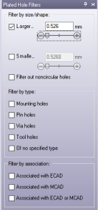
![]() , or Right click on the Plated Holes Item and select Filter out. Using the button makes a filter manager available;
, or Right click on the Plated Holes Item and select Filter out. Using the button makes a filter manager available;
Using this, select the “Larger” checkmark and move the slide to the left as shown.
Next, we will ignore the zero height components.
Click on the application menu button in the upper left corner and select Options.
Then select SOLIDWORKS Import and set “Zero-height components to “Ignore”. Then click OK.
Click “Build Model”
Then in the dialog click “Build”. The process will show in the lower panel.
Your SOLIDWORKS assembly will look like this:
If you believe that there are components missing, you will need to modify the properties of the component in the CircuitWorks interface, or create solid models to add to the library. You may make modifications to the component references and add features to the PCB. The SOLIDWORKS assembly my now be saved back to an ECAD file to communicate the changes to the PCB designer.
This assembly my now be used with other SOLIDWORKS assemblies co complete the design.
If you would like more details about the advanced features of CircuitWorks, please follow our channel Logical Solutions Limited
To get more updates on SOLIDWORKS Follow Us on LinkedIn: Click Here
For more details Like Us on Facebook: Click Here
For videos SUBSCRIBE to our channel: Click Here
Logical technical support Dial @ 040-2418 0011.


